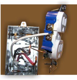
At the circuit breaker box or fuse box, turn off the electrical power. Step 2: Take Out the Existing Electrical Outlet. Remove the mounting screws that are securing the existing electrical. Use a screwdriver or drill to remove the wall plate. Remove mounting screws and gently pull the switch out of the wall box.
Disconnect wires from the existing outlet. Prepare wires by making sure they are. One cable (or pair of wires ) typically supplies power to. The lights on the tester should go out. Fall More Today!
These devices are back and side wire and come in a variety of colors including white, ivory, almond with more colors available to help match your decor. The single screw at the bottom is the grounding screw. Attach both the black and white wires to the screw terminals on the line side. Fasten the black wire to the dark-colored screw and the white wire to the light-colored screw.
Use a 15-amp breaker with 14-gauge wire and a 20-amp breaker with 12-gauge wire. The first outlet is connected to the source and 2-wire cable runs from box to box. All wires are spliced with a pigtail at the devices to pass current to the next. STEP 4: Black (hot) wire connects to a brass or gold screw on one side.
White (neutral) wire connects to a silver screw on the opposite side. Green or copper (ground) wire connects at the bottom of the outlet to a green screw. Secure the connections using a wire nut and wrap them using electrical to tape for extra safety.

I have experienced this myself. Dedicated Circuits. Split Receptacle Wiring. Travel Plug Adapters. Improve Your Business ROI - Get A Better Deal On Gfci Receptacle. This Is The New eBay. Find Gfci Receptacle Wiring Now! GFCI Location Form.
Take off the cover plate and unscrew the outlet from the box. Step Attach the curly white wire from the breaker to the neutral bus. Remove outlet from box while keeping the wires attached to the outlet. Cap off each removed wire separately with a wire nut.

Make sure that they are from the same cable. Variety of leviton gfci receptacle wiring diagram. A wiring diagram is a streamlined traditional photographic depiction of an electric circuit. It reveals the parts of the circuit as simplified forms, as well as the power and signal links in between the tools.
Turn off the circuit breaker or remove the fuse supplying power to the receptacle circuit being worked on. You might have to use a. Collection of two pole gfci breaker wiring diagram. All wiring in such circuits must be 12-gauge or larger.

How to wire up an electrical receptacle in one of two methods: parallel or in series or daisy-chained and the difference between the two. Here we compare wiring an electrical receptacle in series or daisy chained (the most-common practice) with wiring receptacles in parallel on an electrical circuit. Authorized Distributor of Leviton.
No comments:
Post a Comment
Note: only a member of this blog may post a comment.